The next three articles deal with the questions that reach us once a controller is installed and does something unexpected. They concentrate on the two principles in Gasyco's MFC-controlled gas mixers: thermal mass flow controllers and differential pressure controllers with a laminar flow element (LFE). Part 1 is about a single gas. Part 2 covers corrosive gases and pressure surges, Part 3 detection limits and contamination.
That gas is carbon dioxide. CO₂ is part of many mixtures Gasyco's gas mixers produce, from argon/CO₂ shielding gases for welding to CO₂ for cell culture. It is also the gas whose behaviour depends most on the conditions in the installation. Depending on the design, Gasyco's controllers are calibrated either with the real gas at process pressure or with air and converted to CO₂ by calculation. Both refer their readings to standard conditions. How well that reference holds in operation is where CO₂ differs from other gases. Three properties are responsible: CO₂ is heavy, its heat capacity changes with pressure and temperature, and it cools strongly when it expands.
CO₂ is dense enough to circulate inside a heated sensor tube and cools enough to change the temperatures the sensor relies on.
Why does my thermal MFC show flow when it is mounted vertically?
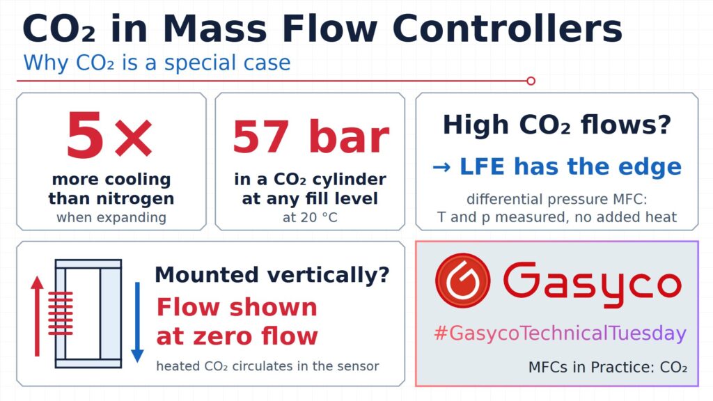
A capillary thermal sensor, as described in article 1, heats a thin tube and measures the temperature difference between its upstream and downstream ends. If the tube stands vertically, the heated gas rises, as smoke rises in a chimney. A small circulation forms through sensor and bypass even when the net flow is zero. The sensor cannot tell this flow from the real one. Zero and span both shift.
The driving quantity is the Grashof number, which grows with the square of the density divided by the square of the viscosity. At equal pressure and 20 °C this ratio is about 3.6 times higher for CO₂ than for nitrogen. Raising the pressure from 1 to 11 bar multiplies the squared density of CO₂ by about 133. A typical capillary controller is specified for nitrogen at 1 bar with at most 0.2 percent error at 90° off horizontal. CO₂ at 10 bar is a different situation.
Hence the rules for capillary sensors: mount upright, with the flow horizontal, especially above 10 bar. The factory zero is set at about 20 °C, atmospheric pressure and upright. If the controller has to be installed with upward or downward flow, re-zero it in its final position, filled with the process gas at process pressure, warmed up and with no flow.
A sensor chip has a far smaller heated volume. It may be mounted in any position, but at higher pressures and with dense gases a slight zero drift can still appear, and above 5 bar or in vertical mounting the orientation should be clarified with the manufacturer. An LFE controller heats nothing. Its orientation has no influence on the measurement, only possibly on the valve, whose plunger has weight.
Excursion: what is the Joule-Thomson effect?
A real gas that expands through a throttle without exchanging heat changes its temperature. The molecules attract each other, and pulling them apart costs energy that comes from their motion. The Joule-Thomson coefficient states how much temperature is lost per bar of pressure drop. According to NIST data at 20 °C, it is 1.14 K/bar for CO₂, 0.38 K/bar for argon and 0.22 K/bar for nitrogen. Hydrogen is above its inversion temperature at room temperature and warms slightly, at −0.03 K/bar.
Throttled from 11 bar to 1 bar, CO₂ loses about 12 K, nitrogen about 2 K. The effect also feeds on itself: at 0 °C the coefficient of CO₂ is already 1.37 K/bar, at −20 °C 1.68 K/bar.
For nitrogen the Joule-Thomson effect is a footnote. For CO₂ it is part of the process design.
Why does my CO₂ regulator freeze?
CO₂ is stored as a liquid. As long as liquid remains, the cylinder pressure is the vapour pressure, about 57 bar at 20 °C, whatever the fill level. The pressure gauge therefore shows nothing about the content; only weighing does. Expanding saturated vapour from 57 to 7 bar at the regulator would, without heat input, end at around −50 °C with part of the gas condensing. That is why CO₂ regulators frost up and why heated regulators exist.
The cylinder cools as well. Evaporating CO₂ takes about 150 kJ per kg at 20 °C. The liquid cools down and the vapour pressure drops, to 35 bar at 0 °C. For higher withdrawal rates, liquid is drawn through a dip tube and evaporated electrically; a 200 W vaporiser handles about 3.2 kg/h. Below 5.18 bar CO₂ cannot exist as a liquid, and a cylinder opened lying on its side can release dry ice snow at −78 °C.
Can liquid CO₂ reach the mass flow controller?
Yes, and it must not. A cylinder with a dip tube delivers liquid when standing upright. Without a regulator, CO₂ condenses again wherever the line is colder than the cylinder: at 0 °C already at 35 bar. Liquid in a sensor tube evaporates on the heater and produces readings without meaning. Seals set a further limit: for CO₂, standard FKM seals are approved up to 10 bar(g) at 50 °C.
What happens to a thermal MFC at high CO₂ flows?
The temperature drop across a throttle depends on the pressure drop, not on the flow. What grows with the flow is the heat needed to warm the gas back up. 740 ln/min of CO₂ throttled by 10 bar needs about 250 W for that. Nitrogen at 1,400 ln/min needs about 70 W. This heat comes from the controller body and the piping. At small flows the body supplies it without noticing. At high flows the body itself cools down.
A thermal sensor is calibrated with gas and body at the same temperature. Cold gas and a cooling body create temperature gradients along the sensor tube, and the sensor cannot distinguish them from flow. In addition, the heat capacity of CO₂ at 1 bar changes by about 0.11 percent per kelvin, so 12 K of cooling change the heat the gas absorbs by more than 1 percent. Pressure matters even more: at 20 °C the heat capacity of CO₂ increases by about 10 percent between 1 and 11 bar, that of nitrogen by under 2 percent. A pressure sensitivity specified for nitrogen does not transfer to CO₂. A real-gas calibration at the actual operating pressure does.
Why do LFE controllers cope better with CO₂ at high flows?
An LFE controller measures the pressure difference across the whole flow, together with absolute pressure and gas temperature. Viscosity and density are recalculated from a real-gas database every 10 ms. The viscosity of CO₂ changes by about 0.33 percent per kelvin, so 12 K would mean 4 percent. Because the gas temperature is measured, that change is corrected rather than read as flow. The temperature sensitivity is specified per degree of inlet gas temperature: below 0.02 percent of full scale per °C at 7 bar a.
Three things make the difference. The LFE adds no heat to the gas, so no internal gradient is part of the measurement. There is no bypass split that cold gas could shift. And the orientation does not matter.
Both principles share one limit. The same LFE controller covers 1,400 ln/min of nitrogen but only 740 ln/min of CO₂, a factor of 0.53. A capillary thermal sensor shows the same factor for its largest CO₂ range. At equal standard volume flow CO₂ has 1.89 times the Reynolds number of nitrogen, and 1/1.89 is 0.53. Both principles need laminar flow, and Part 3 returns to this.
Strengths
- LFE controller: no added heat, temperature and pressure measured and corrected, orientation-independent.
- Capillary thermal controller: high pressures, sensor behind a stainless steel wall.
- Chip-based thermal controller: small heated volume, fast, compact.
Weaknesses
- Capillary thermal controller: chimney effect, pressure dependence of CO₂'s heat capacity.
- Chip-based thermal controller: limited to about 11 bar a, slight zero drift with dense gases.
- LFE controller: only as good as its gas temperature measurement; 1 to 14 bar a.
What should I tell my supplier when ordering a CO₂ mass flow controller?
Inlet and outlet pressure, the maximum flow, the mounting orientation, the supply (cylinder, bundle or tank with vaporiser) and the expected gas temperature at the inlet. These decide between a thermal and an LFE controller and set the calibration conditions. Every mass flow controller in a Gasyco gas mixer is specified with the pressures it will actually run at.
Where does CO₂ sit in the running thread?
Every principle in this series leans on a property of the gas. The thermal principle leans on heat capacity, and CO₂ is the gas whose heat capacity moves most with pressure and temperature. The LFE leans on viscosity, which also moves with temperature but is measured and calculated. The chimney effect adds gravity, the force that made the variable area meter of article 9 work. There it was the measuring principle. Here it is an error.
Conclusion
CO₂ does not make thermal controllers unsuitable. Most CO₂ controllers are thermal and work well. It does mean that orientation, pressure and inlet temperature belong in the specification. At high flows and large pressure drops, a differential pressure controller with a laminar flow element has the advantage. In Gasyco's gas mixers both principles are in use for exactly this reason.