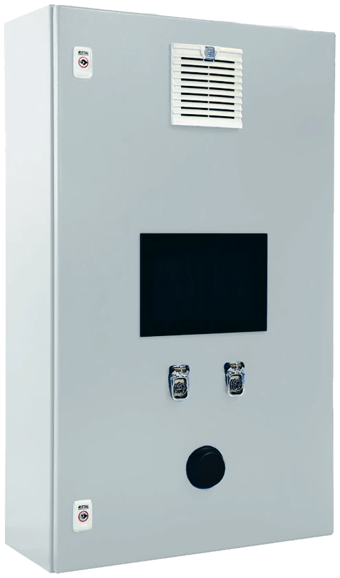

A worked example with 16 manual MAG stations and 4 welding robots: peak demand, average consumption and buffer volume.
We hear this question a lot, and the honest first answer is that the number of welding stations tells you very little. What matters is how much shielding gas each station draws, how many of them weld at the same time, and how much buffer volume the system holds.
It gets interesting when manual and robotic welding share one supply. A manual welder stops constantly to position a part, tack it or check the seam. A robot can weld almost continuously for long stretches. The two produce very different load profiles, and this example shows how to size a mixer around them.
What does the example plant look like?
A metalworking shop runs 16 manual MAG stations and 4 welding robots or cobots. All of them are to be supplied centrally with 82 percent argon and 18 percent CO₂, classified as M21-ArC-18 under ISO 14175. We assume this mixture is suitable and qualified for every welding task in the shop.
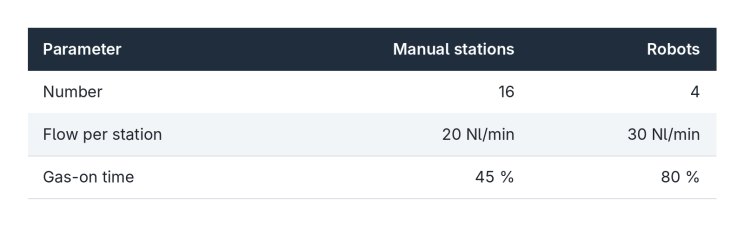
20 Nl/min is a common value for many spray and pulsed arc applications. Air Products cites around 8–12 l/min for thin sheet and 15–20 l/min for thicker material, and notes that mechanised systems typically need somewhat more than manual stations. We therefore use 30 Nl/min for the robots. That is no fixed rule. The right flow depends on gas nozzle, welding current, torch geometry and surroundings, and too much gas can actually weaken the shielding through turbulence.
All values are planning assumptions. We work in standard litres per minute throughout; real figures may need converting to the same reference conditions.
What is the peak demand?
Start with the worst case: all 20 stations drawing gas at once.
16 manual stations × 20 Nl/min = 320 Nl/min
4 robots × 30 Nl/min = 120 Nl/min
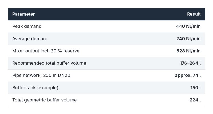
Peak demand: Qmax = 440 Nl/min, or 26.4 Nm³/h.
The supply has to be able to deliver this whenever it happens.
How much gas is used on average?
In practice no station welds without pause. TWI, The Welding Institute, gives a typical arc-on time of about 45 percent for semi-automatic MIG/MAG welding, within a range of 15 to 60 percent, and about 90 percent for automatic welding, within 50 to 100 percent. We use 45 percent for the manual stations and a more cautious 80 percent for the robots.
TWI calls this the duty cycle, a term welders more often use for the rating of the power source. What counts for gas supply is the share of time in which gas actually flows. Pre-flow and post-flow make it somewhat longer than the arc time alone. For simplicity we treat both as equal.
Manual stations: 320 × 0.45 = 144 Nl/min
Robots: 120 × 0.80 = 96 Nl/min
Average demand: Qavg = 240 Nl/min, or 14.4 Nm³/h.
This figure is good for estimating gas consumption and running costs. It is the wrong basis for sizing the mixer. However rarely it happens, all 20 stations can draw gas at the same moment.
What output does the mixer need?
We take the peak demand and add a 20 percent reserve. That is our assumption for this example and no mandated value.
440 Nl/min × 1.2 = 528 Nl/min, or 31.68 Nm³/h.
The mixer has to deliver this quantity of finished mixture reliably at the outlet pressure the central supply requires. Just as important, the mixing ratio has to stay within tolerance whether 440 or 20 Nl/min is being drawn. Selecting an actual unit then also brings in inlet pressure, outlet pressure and pressure losses in the pipe network.
Why do we recommend a buffer tank?
In a central supply, demand changes all the time. Welders stop and start while the robots keep running. Without a buffer, an electronic mixer has to follow each of these changes immediately.
Every dynamic control adjustment comes with a brief control deviation.
Depending on the control behaviour, that shows up in the flow or in the mixing ratio. We therefore recommend drawing directly from the mixer only where consumption is very steady and predictable. With fluctuating demand, a buffer tank belongs in the system. It absorbs short peaks and lets the mixer run more evenly, which directly benefits mixture quality.
How large should the buffer be?
For our GAMI gas mixers we use a simple rule of thumb: the total geometric buffer volume should be about one third to one half of the mixer’s output per minute.
Vbuffer [l] ≈ Qmixer [Nl/min] × 1 min × (1/3 to 1/2)
For our 528 Nl/min:
528 × 1/3 = 176 litres
528 × 1/2 = 264 litres
Recommended total buffer volume: 176 to 264 litres.
This is a guideline for initial sizing. It is no standard and does not replace a dynamic analysis. And the volume does not all have to sit in one vessel.
Can the pipe network count as buffer?
In larger shops, central gas lines hold a considerable internal volume. It can be counted, provided the lines are connected on the pressure side to the buffer system and the permitted pressure swing allows real gas exchange.
Example: 200 m of DN20 steel pipe, 26.9 × 2.6 mm, giving an inner diameter of 21.7 mm.
V = π × d² / 4 × L = π × (0.0217 m)² / 4 × 200 m ≈ 74 litres
With an inner diameter of exactly 20 mm it would be only about 63 litres, so it pays to use the real pipe dimensions.
Counting the full 74 litres, the separate tank only needs 102 to 190 litres. A 150-litre tank gives 150 + 74 = 224 litres, comfortably inside the recommended range.
Why is geometric volume not the same as usable gas?
This point is easy to miss. Litres of vessel volume are not standard litres of gas.
How much gas a buffer can release is set by how far its pressure is allowed to drop.
An example: if the pressure in the 74 litres of pipe falls by 0.5 bar at 20 °C, ideally only about 34 standard litres are released, referred to 0 °C and 1.01325 bar. If the mixer delivered nothing at all, that would cover 440 Nl/min for just under five seconds. On top of that, pressure losses, regulators, check valves or long runs can prevent the full line volume from becoming effective at short notice.
Our rule of thumb is therefore a starting point. Whether the pipe network can be counted in full, and how large the tank really needs to be, is settled against the actual pressure and load profile.
What else matters in practice?
- Turndown: the mixer has to mix accurately even when only two or three manual welders are working.
- Inlet gas monitoring: an empty CO₂ supply has to be detected before a wrong mixture silently enters the line.
- Outlet pressure: it has to hold under all operating conditions.
- Piping: cross-sections, flow velocities and pressure losses have to be designed for peak demand.
- Monitoring and documentation: alarms, data logging and remote access make the whole supply transparent.
Conclusion
Three takeaways. First, simultaneous peak demand sets the mixer output, while the average only tells you the consumption. Second, fluctuating demand calls for a buffer tank. Third, the pipe network can take on part of the buffer, as long as you are honest about how much of it is really usable.
With our digital gas mixer GAMI we design gas mixing systems individually around gas types, flow ranges, operating pressures and mixture-quality requirements. For central supplies we never look at the mixer alone. We always look at the whole supply concept.
A simplified sizing example. Flows, gas-on times and reserve are assumptions; the buffer rule of thumb is a design recommendation by Gasyco GmbH. Final sizing requires checking the actual operating conditions.