Ten articles in this series have dealt with measuring. In a mass flow controller that is only half of the job. The other half is done by a part that rarely gets more than one line on a data sheet: the control valve. It is an orifice whose open area the controller can change. The sensor reports the flow, the PID controller compares it with the setpoint, and the valve opens or closes until both agree.
The same pressure difference that drives the gas through the valve also presses the valve shut.
Which valves are there?
Six designs cover the field from a few cubic centimetres per minute to thousands of cubic metres per hour:
- Direct-acting solenoid valve: a spring closes, a coil lifts. The standard in compact controllers.
- Pilot-operated valve: a small solenoid valve steers the gas, and the gas opens the main valve. For high flows.
- Pressure-compensated bellows valve: a large orifice at very small pressure difference.
- Piezo diaphragm valve: all-metal and particle-free, for small flows in semiconductor fabs.
- Thermal expansion valve: heat lifts the valve head. Historic and slow.
- Process control valve with pneumatic actuator: beyond the compact controller, with a separate meter.
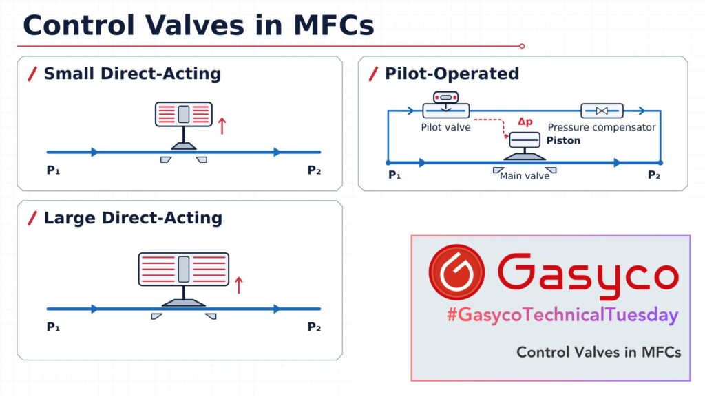
Gasyco's gas mixers are MFC-controlled: every gas component flows through its own mass flow controller. In these mixers three valves do the work, all of the first two designs: a small direct-acting valve in our thermal controllers with a sensor chip, a large direct-acting valve in our differential pressure controllers with a laminar flow element, and a pilot-operated valve in our capillary thermal controllers for the highest flows. This article follows these three.
Why does the pressure decide which valve works?
A valve behaves like the orifice plate from article 2: the flow depends on open area, pressure difference and gas density. Once the pressure drop exceeds about half the inlet pressure, the flow becomes critical, as in the nozzles of article 3, and only the inlet pressure counts. Kv sizing switches to a different formula exactly there. At least 20 percent of the supply pressure should drop across the valve. Below that, the valve has too little authority over the flow.
The pressure difference also acts on the seat: F ≈ Δp × πd²/4. Across a 1 mm orifice at 200 bar this exceeds 15 N, while a valve coil exerts about 5 N. A stronger coil costs power and turns it into heat. The permissible pressure difference of a direct-acting valve therefore falls with its orifice: 24 bar at 0.7 mm, 12 bar at 1 mm, 6 bar at 1.5 mm, 3.6 bar at 2 mm. Multiply each by d² and the result stays between about 12 and 14 bar·mm².
Valve one: the small direct-acting valve
Our thermal controllers with a sensor chip cover ranges up to 450 ln/min of air. The valve seat is chosen at the factory for gas and pressure, from very small seats for the lowest ranges to seats of several millimetres for the highest. Here the force law shows directly: the larger the seat, the lower the permissible pressure, and with the largest seats the working pressure drops from 11 to 8 bar. Large seats are also built as double valves, which share the open area between two plungers, and they draw more coil current.
Its strengths are speed and size: the sensor answers within 50 ms, and the valve is closed without power. Its weakness is the medium. A contaminated valve no longer closes and has to be flushed by opening it fully several times, and substantially different pressure conditions change the control behaviour.
Valve two: the large direct-acting valve
Our differential pressure controllers with a laminar flow element reach 1,400 ln/min of air with a direct-acting valve, at less than 3 bar pressure difference. The low pressure is what makes this possible. Orifice, springs and valve position at the inlet or outlet are chosen at the factory from gas and pressures. At atmospheric inlet pressure the valve needs about 30 percent of its drive before it lifts, more at higher pressure, so the starting point is set for the ordered pressure. If it stays fully open without flow for 20 seconds, the firmware cuts the drive to 75 percent to keep the coil from overheating.
The valve is always normally closed, and the firmware also closes it on a significant fault. With the valve at the outlet, the controller can tare its zero automatically against the closed valve, under full line pressure. The large coil buys independence from a minimum pressure difference. The price is size, power and heat. The response time is 120 ms as a meter and 2 seconds as a controller, measured to SEMI E17, the standard test for a controller's answer to a setpoint step.
Valve three: the pilot-operated valve
Our capillary thermal controllers for the highest flows cover ranges up to 375 m³n/h, with Kv values from 0.6 to 6. With the rule of thumb d = 7.6 × √Kv in millimetres, Kv 6 means a main orifice of almost 19 mm, sized at the factory for gas and process conditions. A coil acting directly on it would need several hundred times the force of a 1 mm valve.
It is an indirect valve with a complete pressure-compensated valve as its pilot. A fixed pressure compensator keeps the pressure difference across a small solenoid valve constant. That solenoid valve sets the pressure difference across a piston, and the piston lifts the main plunger. Inlet and outlet pressure may change without affecting the control.
The coil no longer fights the gas. It only tells the gas where to push.
The limits follow from the principle. Below a minimum pressure difference the piston cannot be positioned, and the pressure difference is limited to 20 bar. If more is present at start-up, a bypass valve is needed. Pressure testing a system with such a valve needs a special procedure, and the settling time is 2 to 4 seconds.
And the other designs?
The bellows valve cancels most of the pressure force with a metal bellows, so a weak coil opens a large orifice, for several hundred litres per minute at minimal pressure difference. It suits low pressure or vacuum and should be mounted upright. The piezo valve bends a metal diaphragm with a large force over a tiny stroke, without sliding parts or elastomers. Such controllers reach helium leak rates below 1 × 10⁻¹¹ Pa·m³/s and cover ranges from 5 sccm to 10 slm. Their limits are the small stroke and hysteresis. Thermal valves in early controllers typically handled 50 to 3,000 cm³/min and were slow. Beyond a few thousand litres per minute, a process control valve sized to IEC 60534-2-1 and leak-tested to classes I to VI of IEC 60534-4 takes over.
What goes wrong in practice?
- An oversized orifice controls the bottom of the range with a small fraction of its stroke and limits the turndown.
- A pressure other than ordered: the valve opens late or does not reach full scale.
- A closed control valve is not a shut-off valve. The valve of a chip-based controller is specified for a leakage of 1 × 10⁻⁶ mbar·l/s helium.
- Particles on the seat keep the valve from closing, hence the inlet filter.
- Normally closed shuts on power loss, normally open opens fully. The process decides which is safe.
Strengths
- Small direct-acting: fast, compact, closed without power.
- Large direct-acting: high flow without a minimum pressure difference.
- Pilot-operated: highest flows, insensitive to pressure changes.
Weaknesses
- Small direct-acting: the pressure limit falls with orifice size, sensitive to contamination.
- Large direct-acting: coil size, power and heat.
- Pilot-operated: needs a minimum pressure difference, limited to 20 bar, slower to settle.
Bonus: Kv, Cv and what “bigger” means
Kv is water in m³/h at 1 bar, Cv water in US gallons per minute at 1 psi, with Cv ≈ 1.156 × Kv. Neither says anything about physical size. In Gasyco's gas mixers the large direct-acting valve is noticeably bigger than the pilot-operated one, although the latter controls several times the flow. One has to supply its whole force from a coil. The other borrows it from the gas.
Where does the valve sit in the running thread?
Every principle in this series leans on a property of the gas. The valve leans on density and, once critical, on the ratio of specific heats, like the orifice plate and the critical nozzle. In a controller this hardly matters, because the sensor closes the loop. The valve only has to change the flow finely and repeatably enough for the sensor to correct it. The variable area meter of article 9 is its mirror image: there gravity sets the force and the area follows the flow. And the pilot valve is the first device in this series that uses the medium's own pressure as its actuator.
Conclusion
The sensor decides how accurately a controller measures. The valve decides at which pressures, over which range and how fast it can act on that measurement. Choosing a mass flow controller therefore starts with two numbers that have nothing to do with the sensor: inlet and outlet pressure. That is why every mass flow controller in a Gasyco gas mixer is specified together with the pressures it will actually run at.