In part one we looked at three subsonic differential pressure designs: the laminar flow element, the orifice plate and the Venturi. All three share one quiet assumption.
We treated the gas as if its density stayed constant while it was being accelerated.
With gases, that only holds up to a point. And once it stops holding, something genuinely surprising happens: the flow through a restriction stops caring about the pressure behind it.
Why the speed of sound becomes interesting with gases
When a gas is accelerated strongly, pressure, temperature and density change together. A liquid can largely be treated as incompressible. A gas cannot.
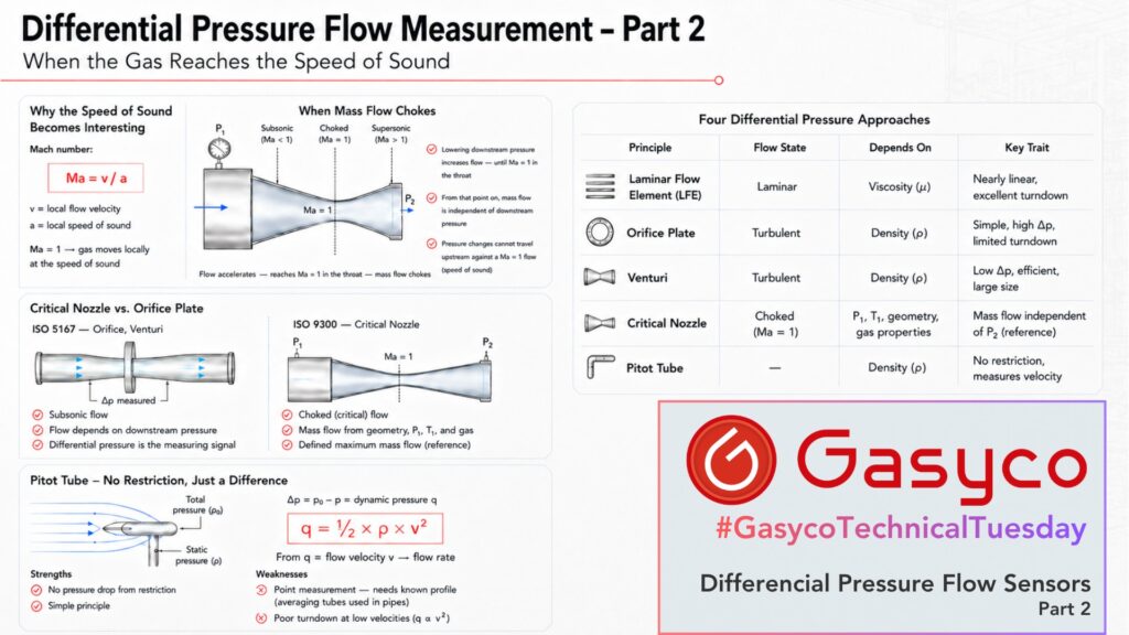
How relevant these compressibility effects become is described by the Mach number:
Ma = v / a
Here v is the local flow velocity and a the local speed of sound. At Ma = 1 the gas moves locally at exactly the speed of sound.
And at a restriction, that is where something special happens.
When the mass flow chokes
Imagine a nozzle whose inlet pressure is held constant.
If the pressure behind the nozzle is lowered, the flow velocity and with it the mass flow first increase. Lower it further and the flow keeps rising. At some point, however, the gas reaches Mach 1 in the narrowest cross-section of the nozzle.
From that point on, the maximum possible mass flow for the given inlet conditions has been reached. This is called critical or choked flow. Lowering the downstream pressure further no longer increases the mass flow.
The physical reason is elegant. Pressure changes travel through a gas at the speed of sound. If the gas in the throat is already moving at exactly the speed of sound, information about a further pressure drop downstream can no longer travel back upstream against the flow. The region before the throat never learns that anything changed.
The mass flow is thereby decoupled from the downstream pressure.
A common misreading
It is worth clearing up one point that causes regular confusion:
The speed of sound is not the maximum possible gas velocity.
Mach 1 is reached in the throat of a purely convergent nozzle. Behind a suitably designed convergent-divergent section, the gas can accelerate well beyond it, which is exactly how supersonic wind tunnels and rocket nozzles work.
What choking limits is therefore not the gas velocity in general. It is the mass flow through the critical cross-section for given inlet conditions.
Measuring mass flow without a flow sensor
This is what makes critical nozzles so interesting for measurement.
Under choked conditions the mass flow is essentially determined by four things: the cross-sectional area of the nozzle throat, the absolute pressure upstream of the nozzle, the absolute gas temperature upstream of the nozzle, and the thermodynamic properties of the gas.
In practical terms:
- larger throat area, higher mass flow
- higher inlet pressure, higher mass flow
- higher gas temperature, slightly lower mass flow at the same pressure
Notice what is missing from that list. There is no downstream pressure, and there is no flow sensor. The mass flow follows from geometry, inlet state and known gas properties alone.
That is why critical nozzles are used as highly stable references for calibrating gas flow instruments. ISO 9300 describes geometries and calculation methods with which the mass flow can be determined within defined limits without individually flow-calibrating the nozzle. A well-made nozzle has no real drift mechanism, because there is nothing in it that measures.
But where is the catch?
The decisive limitation sits in the word critical.
The relationship only holds as long as the nozzle is genuinely operated in the choked state. If the pressure difference is too small and Mach 1 is not reached in the throat, the flow depends on the downstream pressure again, and the simple determination from the inlet conditions stops working.
Typical drawbacks follow from that:
- a minimum pressure ratio across the nozzle is required
- a significant permanent pressure loss has to be accepted
- a fixed throat area delivers essentially a fixed mass flow at constant inlet pressure
- for a variable setpoint, the inlet pressure has to be controlled or the effective throat area changed
- gas type and gas temperature must be known
For a classic mass flow controller with a freely variable setpoint, a single sonic nozzle is therefore of limited use. For calibration rigs, reference flows and very stable fixed gas streams, the principle is outstanding.
Critical nozzle and orifice plate are not the same thing
An orifice plate can also reach a critical flow state if the pressure ratio is large enough. That does not make the two devices equivalent.
ISO 5167 covers orifice plates, Venturis and comparable primary elements explicitly for flow that stays subsonic across the whole relevant measuring range. The flow is determined from the measured differential pressure.
ISO 9300 takes the opposite approach. The nozzle is deliberately operated so that critical velocity is reached in the smallest cross-section. The measuring signal is then no longer primarily the differential pressure, but the known relationship between nozzle geometry, inlet state and critical mass flow.
That makes the critical flow nozzle a genuinely interesting boundary case: physically it sits between a differential pressure measurement and a defined mass flow generator.
Bonus: where does the Pitot tube fit?
The Pitot tube is also a differential pressure method, but with a different approach again. It creates no defined restriction at all.
Instead, a measuring port faces the flow head-on. There the flow is brought locally almost to rest and the total pressure is captured. A second port measures the static pressure. The difference between the two is the dynamic pressure, and at low Mach numbers q = ½ × ρ × v². From this the flow velocity follows.
So a Pitot-static tube really is a differential pressure flow meter. It simply does not generate the pressure difference with a classic restriction.
Two limits are worth knowing. It is a point measurement, so it only yields a flow rate if the velocity profile is known, which is why averaging Pitot tubes with several ports are used in pipes. And because the pressure difference again follows the square of the velocity, the turndown at low velocities is poor.
Conclusion
Differential pressure flow measurement is far more versatile than the name suggests.
In a laminar flow element, viscous friction produces an almost linear relationship between flow and pressure drop. In an orifice plate or a Venturi, it is mainly the acceleration of the fluid that sets the differential pressure. And in a critical nozzle, the compressibility of the gas is deliberately exploited until the speed of sound is reached in the throat and a defined maximum mass flow establishes itself.
The Pitot tube adds a fourth variation: no restriction at all, just a local comparison between total and static pressure. It is the same principle used to measure airspeed on aircraft.
Taken together, the two parts of this article show why Reynolds number, flow state and Mach number are not theoretical side topics. They decide directly which measuring principle works, and which equations may be applied at all.