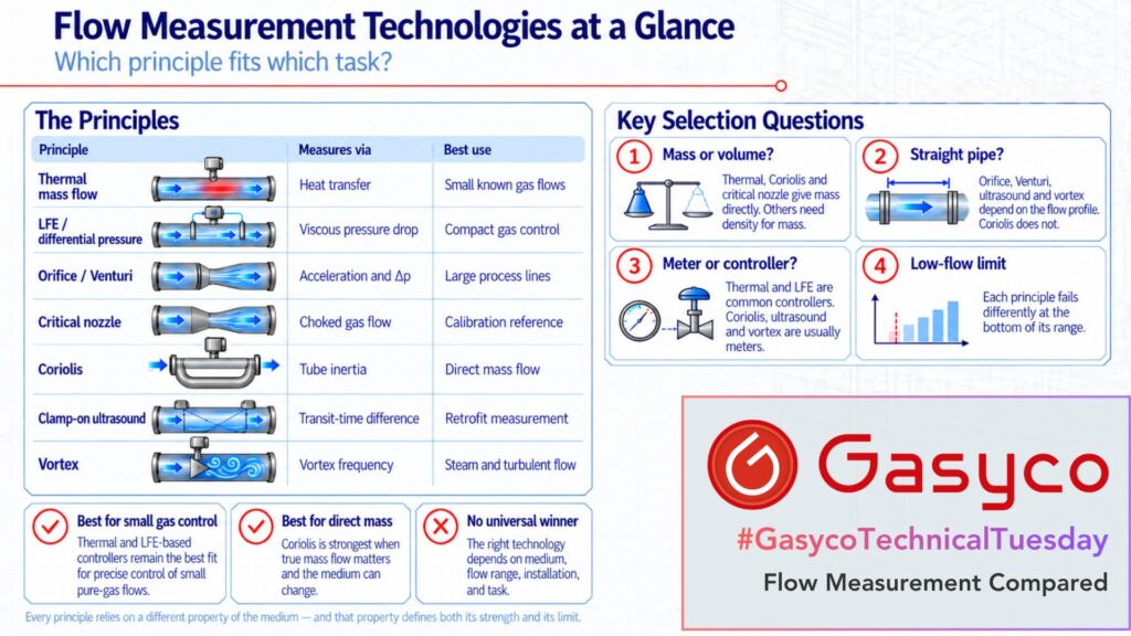
Over seven articles this series has measured flow through heat, pressure differences, the speed of sound, a vibrating tube, gear teeth, sound waves and vortices behind an obstacle. This article puts them side by side, in this order:
- Thermal mass flow
- Differential pressure: LFE, orifice plate, Venturi
- Critical nozzle
- Coriolis
- Gear meter
- Clamp-on ultrasound
- Vortex
- What connects them
- At a glance: strengths, weaknesses, best use
One question has run through the whole series.
Every measuring principle leans on a property of the medium, and that property decides where it works and where it fails.
Our perspective has stayed the same: our gas mixers measure and, above all, control small flows of pure gases with high accuracy. Several principles in this series do not fit that task. We covered them anyway and said so.
1. Thermal: why does heat give mass flow directly?
A flowing gas absorbs heat in proportion to its mass flow times its specific heat capacity. The measurement therefore yields mass flow without separate pressure and temperature compensation. Three designs share the principle: a wetted sensor chip in a bypass, a capillary with external heated windings, and a sensor in the main flow.
The price is gas dependence. The sensor follows heat capacity and thermal conductivity, while in bypass designs the split between sensor and main path follows viscosity. Gas conversion factors are therefore approximations, and for strongly differing gases the additional error can reach several percent. Capillary sensors add a zero offset that depends on mounting orientation, most noticeable with hydrogen or helium at low pressure.
2. Differential pressure: why does the LFE behave so differently from the orifice plate?
All three devices from our second article turn a pressure difference into flow, but the physics behind the Δp differs. In the laminar flow element, viscous friction in narrow channels dominates, and Q ∝ Δp / μ is roughly linear. In the orifice plate and the Venturi the gas is accelerated, Δp ∝ Q², and density enters.
That square-root law decides the bottom of the range. At 25 percent of full scale an orifice produces only about 6 percent of full-scale Δp, which limits a single orifice run to about 3:1 to 4:1. The LFE reaches 50:1 and beyond, which is why it sits in compact mass flow controllers while the orifice sits in pipelines. The Pitot tube, a point measurement of dynamic pressure, shares the square-root weakness.
3. Critical nozzle: what changes at the speed of sound?
Once the gas reaches Mach 1 in the throat of a nozzle, pressure changes downstream can no longer travel upstream. The mass flow then depends only on throat area, absolute inlet pressure, inlet temperature and the gas data, specifically the ratio of specific heats and the gas constant. There is no flow sensor and nothing that could drift. ISO 9300 describes nozzles whose mass flow can be determined without individual flow calibration, which makes them stable references for calibration rigs.
4. Coriolis: why is it the first principle to break the pattern?
The flowing mass itself changes the vibration behaviour of a measuring tube.
The time delay between two pickoffs, in the microsecond range, is proportional to mass flow, and the resonant frequency yields density. No gas property is needed to turn the primary signal into mass flow. Because the entire mass acts on the tube, the meter is largely indifferent to the velocity profile and needs no straight inlet runs.
For small gas flows the low density is the problem. Very little mass moves through the tube, and zero stability becomes the limiting factor.
5. Gear meter: what does counting volume directly buy you?
Two meshing gears carry defined volumes from inlet to outlet, and every tooth produces a pulse. Good instruments reach a repeatability around ±0.05 percent of reading over spans of roughly 10:1 to 100:1.
The weak point is slip through the necessary clearances. Slip depends on viscosity, and viscosity depends on temperature; with oils, ten kelvin can nearly halve it. The K-factor is therefore a curve rather than a constant. Gases defeat this design almost completely: low viscosity, compressibility and no lubrication.
6. Clamp-on ultrasound: what does it cost to stay outside the pipe?
Sound travels slightly faster with the flow than against it. From both transit times the velocity follows with the speed of sound cancelling out, measured through the pipe wall with no pressure drop and no process connection.
On gas this is acoustically hard. At normal incidence, well under one ten-thousandth of the sound energy crosses a steel-to-air boundary. The profile correction factor moves from about 0.75 in laminar flow to 0.90 to 0.97 in turbulent flow. A 2026 study on natural gas measured deviations of up to 9 percent within ten diameters downstream of a single bend.
7. Vortex: why does the fluid stay out of the reading?
Behind a bluff body, vortices shed at a frequency proportional to velocity, and in the linear range the K-factor depends only on geometry. A meter calibrated on water can go into a steam line.
The flow has to be turbulent, though. Application rules from Shell and TNO found no signal at all below a Reynolds number of 5,000. Signal amplitude scales with ρ × v², so low gas density raises the minimum velocity.
8. What connects them?
Thermal instruments lean on heat capacity. The LFE uses viscosity as its measuring effect, while the gear meter fights the same property as leakage, with the opposite sign. Orifice plate and Venturi depend on density, the critical nozzle on the ratio of specific heats. Coriolis needs none of these for the mass measurement. Clamp-on ultrasound cancels the speed of sound, but viscosity returns through the profile factor. The vortex meter keeps fluid properties out of its reading and uses them as an entry condition instead.
Four further questions came back in almost every article and decide most selections.
- Mass or volume? Thermal, Coriolis and the critical nozzle deliver mass. LFE, orifice, Venturi, gear meter, ultrasound and vortex deliver volume or velocity and need density to get to mass.
- Straight pipe? Orifice, Venturi, Pitot tube, clamp-on ultrasound and vortex depend on the velocity profile. Coriolis and the gear meter do not.
- Meter or controller? Thermal and LFE instruments dominate compact controllers. Coriolis, gear, ultrasonic and vortex instruments are mostly meters feeding a separate valve or pump.
- What happens at the bottom of the range? Square-root devices lose their signal, Coriolis runs into zero stability, the gear meter into slip and friction, ultrasound into vanishing time differences, and the vortex meter stops seeing flow at all.
Small flows are where every principle shows its true limit, and each one fails there in its own way.
9. At a glance: strengths, weaknesses, best use
| Principle | Best for | Strengths | Weaknesses |
|---|---|---|---|
| Thermal mass flow | small, clean, known gas flows that have to be controlled, as in dosing and gas mixing. | mass flow without pressure and temperature compensation, high sensitivity at small flows, compact controllers | calibrated per gas, sensitive to deposits and condensation, capillary designs depend on mounting orientation |
| Laminar flow element | small gas flows in compact controllers where the gas data is known. | nearly linear, turndown of 50:1 and beyond, fast | narrow channels clog, needs viscosity and gas temperature, pressure drop is part of the principle |
| Orifice plate and Venturi | large pipes, high pressures and high temperatures, where a standardised device matters more than range. | simple and standardised in ISO 5167, no moving parts, Venturi with low pressure loss | square-root law limits turndown to about 3:1 to 4:1, needs straight runs, orifice with high pressure loss |
| Critical nozzle | as a calibration reference or for fixed, very stable gas flows. | mass flow from geometry, inlet state and gas data alone, no drift mechanism | needs a minimum pressure ratio, high pressure loss, a variable setpoint requires controlling the inlet pressure |
| Coriolis | direct mass measurement with changing media, for liquids and for safety-related measurements. | true mass flow independent of composition, density as a by-product, no straight runs | expensive, zero stability limits small gas flows, sensitive to deposits, pipe stress and vibration |
| Gear meter | small, viscous, clean liquid flows and dosing. | repeatability around ±0.05 percent, high resolution, no straight runs | K-factor shifts with viscosity and therefore temperature, wear and particles, unsuitable for gases |
| Clamp-on ultrasound | retrofit, temporary and verification measurements, and for large pipes. | non-invasive, no pressure drop, no contact with the medium | pipe geometry must be known, weak signal on gas, large errors behind disturbances, tiny time differences at low velocity |
| Vortex | steam and for turbulent, steady, single-phase gas and liquid flows in larger lines. | K-factor independent of the fluid within its range, no moving parts, no zero drift | no signal below Re 5,000, minimum velocity rises as density falls, counts vibration and pulsation, long straight runs |
Conclusion
“Which flow meter is best?” has no answer on its own. It becomes answerable once medium, flow range, installation and task are on the table. For small flows of pure, known gases that have to be controlled precisely, the series kept arriving at thermal and LFE-based controllers. For most other tasks another principle is the better choice.