Thermal mass flow devices are among the most established technologies for measuring and controlling gas flows. Their principle is based on a simple physical relationship:
A flowing gas absorbs heat. How much heat it absorbs depends on how much mass passes by and on the specific heat capacity of that gas.
That is the decisive point. Because the heat uptake is proportional to mass flow times heat capacity, the measurement yields a mass flow directly – no separate pressure and temperature compensation is needed.
How this heat transfer is measured, however, differs considerably. Three designs are particularly relevant in practice.
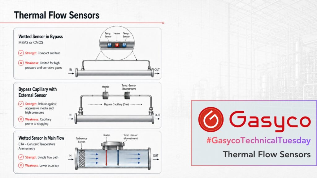
1. Wetted Sensor in a Bypass
Only a defined portion of the total gas flow is directed through the actual sensor. The rest flows through a parallel main path.
This split only works if both paths are flowed through laminarly. Only then is the pressure drop proportional to the flow rate, and only then does the ratio between sensor flow and main flow stay constant. That is why a laminar flow element sits in the main path. If a device is driven far beyond its range, the split becomes flow-dependent – this is the real technical limit of the design.
Inside the sensor path, heater and temperature sensors sit on a small chip in contact with the gas. The flowing gas shifts the temperature profile created by the heater, and the resulting temperature difference gives the flow rate. The sensor structures themselves are covered by a thin passivation layer, so the bare heating element does not touch the medium.
Strengths
- very compact design
- low thermal mass, therefore fast response
- high sensitivity at low gas flow rates
- the full-scale value can be shifted over a wide range through different bypass ratios
Weaknesses
- the sensor surface is in contact with the gas
- deposits, condensation or contamination affect the heat transfer
- wetted materials must be compatible with the medium
- a changing flow split changes the reading
- the turndown within a single calibration stays limited, typically around 1:50 to 1:100
This design is particularly suitable for clean, dry and non-corrosive gases. Modern compact sensors of this type are manufactured using micromechanical processes – more on that below.
2. Bypass Capillary with External Sensor Elements
The traditional capillary sensor also directs only part of the total flow through a bypass.
The key difference lies in the sensor design: the gas flows through a thin metallic capillary, while the sensor elements sit on the outside of it. In most designs these are two self-heating resistance windings that act as heater and temperature sensor at the same time. The sensor elements therefore never touch the medium.
Without flow, the temperature distribution is largely symmetrical. When gas flows, heat is carried downstream and a measurable temperature difference appears.
Strengths
- the actual sensor elements are not wetted
- wetted materials can be clearly defined
- therefore also suitable for chemically more demanding gases
- well-established technology for very low gas flow rates
- designs for high process pressures are available
Weaknesses
- small capillary cross-sections are sensitive to particles and deposits
- contamination can also alter the flow split between main flow and sensor flow
- the higher thermal mass limits response speed
- sensitive to mounting orientation: free convection inside the capillary causes a zero offset that depends on how the device is installed, most noticeably at low pressures and with light gases such as hydrogen or helium
The small bypass capillary is therefore both the strength and the weakness of this technology. It enables highly sensitive measurement of low flow rates but places greater demands on gas purity, filtration and installation.
3. Wetted Sensor in the Main Flow
The third design uses no separate sensor bypass. The thermal sensor sits directly in the main gas flow.
A common approach is anemometry. A heated element is kept at a defined temperature above the gas temperature. In industrial gas instruments this is usually realised by holding a constant temperature difference to a second, unheated sensor that measures the gas temperature. The higher the mass flow, the more heat the passing gas removes, and the more heating power is required.
One note on terminology: this design is mainly found in flow meters and less often in classic compact controllers. Insertion probes in particular are measuring devices, not controllers.
Strengths
- no narrow sensor bypass required
- low additional flow resistance is possible
- the flow path is far less prone to clogging
- well suited for higher flow rates and larger pipe diameters
- can be installed directly into pipelines as an insertion probe
Weaknesses
- the sensor is directly exposed to the process gas
- contamination or condensation acts directly on the heat transfer
- it is a point measurement, so flow profile, inlet runs and pipe cross-section matter
- the characteristic curve is strongly non-linear – the heating power rises roughly with the square root of the mass flux – and requires heavy linearisation
- as a result, the accuracy over the reading is usually lower than with a well-calibrated bypass device
- bypass systems remain more sensitive at very low gas flow rates
This design is therefore particularly common for consumption and flow measurements in larger compressed-air and process-gas pipelines.
The Common Strength – and Weakness – of Thermal Measurement
All three designs rely on the thermal properties of the gas: primarily the specific heat capacity, and additionally the thermal conductivity. A thermal device therefore has to be calibrated for a specific gas or corrected using appropriate gas data.
With bypass designs there is a second dependency that is often overlooked. The sensor signal follows heat capacity and thermal conductivity, but the bypass split follows the viscosity of the gas. Two completely different physical properties.
This is exactly why gas conversion factors are only approximations. For gases with similar properties they work well. For strongly differing gases, or for varying mixtures, the additional error can reach several percent. Where accuracy matters, the device should be calibrated on the actual gas or gas mixture.
Where Do Thermal Devices Stand Compared with Other Technologies?
Thermal devices show their greatest strengths at low gas flow rates, with high repeatability, compact designs and known gases. This explains their widespread use in laboratory, dosing and gas-mixing applications.
Differential-pressure systems determine the flow from the pressure drop across a defined flow element. They can respond particularly quickly and provide several process variables at the same time. They are not gas-independent either: with a laminar element the dominant property is viscosity, and converting to mass flow additionally requires the density derived from pressure and temperature.
Coriolis systems measure mass flow directly through the inertia of the flowing medium and are therefore largely independent of gas type and composition. For gases, however, the low density is the catch. Zero-point stability limits the usable range at low flows, pressure drop and vibration sensitivity have to be considered, and the instruments are considerably more expensive. That is why Coriolis is not the standard in gas dosing, even though it is the more direct principle.
There is therefore no single best technology. Flow range, gas composition, gas purity, pressure, required response time and measurement accuracy determine which principle is most suitable.
Bonus: What Do MEMS and CMOS Mean?
MEMS – Micro-Electro-Mechanical Systems – does not describe a separate fourth flow architecture. The term refers to the micromechanical manufacturing of very small sensor structures: heaters, temperature sensors and flow channels are etched into a silicon chip.
CMOS describes the semiconductor process used for that chip – and above all the fact that the signal-processing electronics sit on the very same chip. The best-known example is Sensirion’s CMOSens technology, which combines sensor element, amplification, digitisation and the stored calibration data on a single silicon chip. The benefit is not a different measuring principle but a cleaner signal: the weak analog signal is digitised exactly where it is generated, which improves EMC robustness and long-term stability.
A sensor can therefore be a MEMS structure, produced in a CMOS process, working as a wetted sensor inside a bypass – all at the same time. “MEMS”, “CMOS”, “bypass” and “wetted” describe different aspects of one device and should not be seen as competing technologies.
Conclusion
The term “thermal MFC” can describe sensors with very different mechanical designs.
- Wetted sensor in a bypass: compact, sensitive and fast.
- Bypass capillary with external sensor elements: established, well suited for very low flow rates, with clearly defined wetted materials.
- Wetted sensor in the main flow: simple flow path, particularly interesting for higher flow rates.
The underlying principle stays the same: mass flow is determined through the heat transfer caused by the flowing gas.