Over six articles this series has measured flow through heat, through pressure differences, through the inertia of a vibrating tube, by counting volumes between gear teeth and by timing sound across a pipe. The vortex flow meter places an obstacle in the flow on purpose and counts what it sheds.
Anyone who has heard a wire sing in the wind has heard the principle. The wire sheds eddies alternately from each side, and their frequency rises with the wind speed.
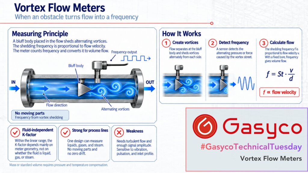
Behind a bluff body, the flow sheds vortices at a frequency proportional to its velocity.
One note on scope. We do not use this technology. Our gas mixers measure and, above all, control small flows of pure gases accurately. A vortex meter needs turbulent flow and a minimum of momentum in the gas before it produces a signal at all. As this article will show, small gas flows at low pressure are exactly where both run out.
What happens behind the bluff body?
A vortex meter is a short pipe section with a bar across its bore, usually of trapezoidal or delta cross-section. At its sharp edges the boundary layer separates, rolls up into a vortex and detaches, alternately on each side. Downstream a regular double row of counter-rotating vortices forms, the Kármán vortex street.
The shedding frequency follows f = St × v / d, where v is the flow velocity, d the width of the bluff body and St the Strouhal number. The design goal is a body shape for which St stays constant over a wide range. There, frequency is proportional to velocity and, with a fixed bore, to volume flow. The manufacturer determines this constant by calibration and states it as the K-factor, in pulses per unit volume.
The frequencies are modest. For liquids, application guidelines from Shell and TNO, based on tests of six makes, list 7 to 100 Hz for DN 50 and 0.5 to 4 Hz for DN 150.
Why does the fluid hardly matter?
Within its linear range, the K-factor depends on the geometry of the meter and not on the fluid.
Manufacturers state this explicitly. One current data sheet declares that above a Reynolds number of 10,000 the K-factor is independent of velocity, viscosity and density, and of whether the meter sees steam, gas or liquid. A meter calibrated on water can go into a steam line.
What does shift the K-factor is geometry. When the meter body warms up, bore and bluff body expand, and OIML D 25 gives the correction as K = K0 × [1 − 3α × (t − t0)], with α the thermal expansion coefficient. For stainless steel, Shell and TNO quote −0.05 percent per 10 K. The edges matter too, because they fix where the flow separates. One manufacturer states that its meters stay within specification as long as wear rounds the edges by no more than 1 mm in non-abrasive, non-corrosive media.
There are no moving parts, and the zero cannot drift: no flow, no vortices, no pulses. It can be faked, though. Pipe vibration at standstill produces pulses too, hence the low-flow cutoff in every vortex transmitter.
How is a vortex detected, and what is actually measured?
Each vortex leaves a local low pressure on its side of the body, so body and wake experience an alternating force. Piezoelectric or capacitive sensors in the bluff body or in a paddle behind it pick this up.
The amplitude of this force is not proportional to velocity. Shell and TNO give it as S = C × ρ × v², the same dynamic pressure that drives the orifice plate in our second article. But the force only has to rise above the noise; the measured value comes from the frequency, which is linear. This is how a vortex meter escapes the square-root trap of the orifice plate, above a threshold.
The frequency delivers volume at operating conditions. Mass or standard volume needs density, so vortex meters for steam and gas are often combined with pressure and temperature measurement. Some meters measure both at one point inside the meter body.
Where does the measuring range end?
At the bottom, two separate limits apply, and the higher one wins.
The first is the Reynolds number, and with it viscosity. Shell and TNO found that below Re 5,000 the meters recognised no flow at all, that between 5,000 and 20,000 the frequency was not linear with flow, and that above 20,000 it was. The data sheet mentioned above specifies below 1 percent of reading for gas above Re 10,000 and below 5 percent between 5,000 and 10,000.
The second is signal amplitude, and here density enters. The same data sheet gives a minimum velocity of 12 m/s at 1 kg/m³ in factory setting, scaling with 1/√ρ. By our own calculation from that formula, nitrogen at atmospheric pressure in a 15 mm bore needs about 11 m/s, roughly 120 litres per minute. The Reynolds number there is about 11,000, just above the 10,000 that data sheet requires. By the stricter Shell and TNO threshold of 20,000, the limit moves to about 210 litres per minute. At 4 bar absolute the minimum velocity halves.
The Shell paper shows the consequences of ignoring this. In three refinery projects between 1990 and 1995, 180 of 1,060 vortex meters had to be replaced. Some reached a turndown of only 2:1 because alarm and trip settings sat below the low-flow cutoff. Oversized meters were a main cause.
At the top, the same data sheet keeps gas below Mach 0.3. Liquids are limited by cavitation, since the lowest pressure, at the bluff body, must stay above the vapour pressure. For that reason OIML D 25 and Shell both want control valves downstream of the meter.
Why do vibration and pulsation matter so much?
A meter that counts a frequency will count any frequency that reaches its sensor. Shell and TNO found that most detection principles pick up pipe vibration above about 0.25 g, and that the effect grows at low density and low flow, where the vortex signal is weakest.
Flow pulsation is more treacherous. In TNO’s tests the vortex street locked onto the pulsation when the shedding frequency was near half, one, one and a half or two times the pulsation frequency. The shedding frequency then follows the pulsation instead of the flow. This can happen at pulsation amplitudes as low as 3 percent. Only with shedding frequencies above four times or below half the pulsation frequency did the error stay within 2 percent. Typical sources are reciprocating compressors and pumps; the usual remedy is a different meter size.
How much straight pipe does it need?
The vortex meter belongs to the profile-sensitive group, with the orifice plate and clamp-on ultrasound. Shell and TNO measured shifts of +0.4 to +1 percent on 3-inch meters with a 90° elbow 10 diameters upstream, and at most +0.4 percent at 40 diameters. Manufacturers ask for 20 diameters after a single elbow, 40 after two elbows out of plane and 50 after a control valve, or 35 as a general rule. One notes that even the orientation of the bluff body relative to the elbow plane matters, and that such shifts normally leave repeatability intact, so they can be corrected.
Strengths
- Linear frequency output; K-factor independent of the fluid in the linear range
- Liquids, gases and steam with one design
- No moving parts, no zero drift
- Repeatability of about 0.1 percent for gases and 0.2 percent for liquids (Shell/TNO)
Weaknesses
- No signal below Re 5,000, non-linear up to 10,000 to 20,000
- Minimum velocity rises as gas density falls
- Picks up pipe vibration and locks onto flow pulsation
- Long straight inlet runs; sensitive to swirl
- Single-phase only; OIML D 25 names wet steam as a case to avoid, though some newer meters detect it
- Measures volume; mass needs pressure and temperature
- Pressure loss, rising steeply in reduced-size meters; cavitation in liquids
Bonus: what is a swirl meter?
The swirl meter is often filed under vortex meters, but it is a separate design. A fixed guide at the inlet sets the whole flow rotating. Where the bore widens again, the vortex core is forced into a secondary spiral motion around the pipe axis, a precession whose frequency is proportional to flow and is picked up by a piezo sensor. Because the meter creates its own defined swirl, upstream disturbances matter far less. A current swirl meter data sheet gives typical runs of 3 diameters upstream and 1 downstream.
Where does it sit against the other principles?
Our running thread asks which property of the medium each principle depends on. The vortex meter gives a new answer.
The fluid properties do not enter the measured value, but they decide whether there is a measured value at all.
Viscosity is the clearest case. The laminar flow element uses it as its measuring effect, the gear meter fights it as leakage, and clamp-on ultrasound lets it back in through the profile factor. The vortex meter uses it as an entry condition. This makes the LFE and the vortex meter opposites: one needs laminar flow, the other turbulent flow.
Density plays a double role. It sets the signal amplitude through ρv², like the Δp of the orifice plate, but only as a threshold. And it is needed again to turn volume into mass. Coriolis broke the pattern by measuring mass without any fluid property. The vortex meter breaks it for volume, within its range.
Vortex meters are meters; in a control loop they feed a separate valve. And at the bottom of the range they do not fade out gradually like a square-root device. They turn non-linear, and then they read zero.
Conclusion
The vortex meter is the process industry’s workhorse for steam and a strong option for gases and liquids wherever flow is turbulent, steady and single-phase. It has nothing to wear except edges, and its K-factor survives a change of fluid. Its limits lie in the conditions around it: enough Reynolds number, enough density, a quiet pipe, enough straight run. The small gas flows in our mixers often fall short of the first two, which is why we rely on thermal mass flow controllers.